You may
Note
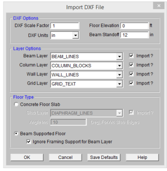
You may import columns, beams, walls and a project grid. Each DXF file should contain only one Floor level. You have several options available for controlling how DXF files are imported. They are as follows:
Select the units you used in the CAD model. The options are none, inches, feet, mm, cm, and meters.
Enter the scale factor that will scale the DXF file to its full size. For instance, if you had created a scaled model in AutoCAD at a scale of 1/4"=12", then the appropriate scale factor to produce a full size RISAFloor model would be 48.
Enter the desired elevation for the new floor level that will be created from the DXF file.
Note
In CAD drawings, beams are not typically drawn all the way to the working point where they connect. Instead, they are shortened by a standoff distance at each support. Enter the maximum standoff distance used in the DXF file. A typical value would be 12 inches. RISAFloor will use this distance when determining the supports for each beam.
Note: this entry will be ignored if you also have the Ignore Framing Support for Beam Layer checkbox selected.
Specify the layer where the column blocks exist. The program will search for any blocks in this layer and import them as column locations.
Note
Enter the layer where the beam data is defined.
Note
Enter the layer where the wall data is defined. Walls must be defined as POLYLINES or they will not be imported. The width of the Polyline will determine the thickness of the wall element in RISAFloor.
Note
Enter the layer where the project grid data is specified. This will replace any existing project grid data and replace it with the project grid from the DXF file. Therefore, it may be desirable to un-check the Import? box to prevent the current Project Grid from being replaced.
Cantilevered beams Cantilever beams are unsupported at the cantilever end. Therefore, they are not imported unless the Ignore Framing Support for Beam Layer option is checked. When this box is checked, the cantilevers will still require some manipulation within RISAFloor. However, your basic model geometry and secondary framing will be more complete.
The Floor Type can be set to Concrete Floor Slab or Beam Supported Slab. A RISAFloor ES license is required in order to create a Concrete Floor Slab.
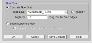
The Slab Layer will be imported based on the layer selected. Concrete Floor Slab don't require framing of beams, columns or walls to be imported however all the options above can be imported with the slab if they are checked on.
The slab will break an arc into straight line elements automatically during the import. This number indicates the number of degrees that an imported arc should be broken into.
Although it is not specifically noted in the AutoCAD documentation, the implied default vertical axis is the positive Z-axis of the current User Coordinate System.
The default vertical axis in RISA is usually the positive Y-axis and may be specified on the Model Settings. When you export your model to a DXF file, you can have the program automatically rotate your geometry to match the vertical axis of your CAD program.
This is a Yes/No check box. If you check the box “Yes”, the program will translate Section Set Labels to layer names. Layers will be created in the DXF file corresponding to the section set labels in the RISA model. A “Yes” choice here overrides any layer name entered for the member layer.
The program will add a prefix to each section set layer to designate what type of material that section is. The prefixes are as follows:
| Material Type | Layer Prefix |
|---|---|
| Cold Formed Steel | CF_ |
| Concrete | CN_ |
| Hot Rolled Steel | HR_ |
| General Materials |
GN_ |
| Wood | WD_ |
For example, let’s say you have designed a structure with Hot Rolled steel section sets called "Column"and " Girder", as well as a Wood section set called "Joist". If you type in a member layer name such as "STEEL" then all members, regardless of size, will appear on a layer named "STEEL". However, if you choose “Yes” for the translate section sets to layers option, then all the member that are assigned to the Column section set will appear on a layer named "HR_Column", the girders on a layer named "HR_Girder", and the joists on a layer called "WD_Joist".
This is a Yes/No choice. If you choose “Yes”, the program will take members and assign them to a layer which uses their shape label as the layer name. Layers will be created in the DXF file corresponding to the shape labels in the RISA model. A “Yes” choice here overrides any layer name entered for the member layer.
Note:
Points, columns, walls, beams, and text can be exported to an ASCII DXF file. Any other information such as the boundary conditions, loads, member end releases, etc. are not exported. You have several options available for controlling how DXF files are exported as follows:
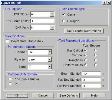
You can export all the floors of the model or individually select the floor you wish to export.
Enter the factor that will cause the full scale RISA model to be scaled up or down to the desired drawing scale. For example, if you created a full scale model that you wanted scaled down to 1/4"=12", the factor would be 0.020833, which is (.25/12).
Select the units you desire the CAD model to be created in. The options for the DXF units are none, inches, feet, mm, cm, and meters.
You can export the project grid bubbles either as Circles or Hexagons.
You can create DXF files that give the Beam Size, Camber, End Reactions, and Number of Studs. Alternatively, you can create a DXF file that only shows the beam depth.
Typically beams are not drawn all the way to the ends of the beams or columns to which they connect. Instead, they are shortened by a standoff distance at each support. Enter the standoff distance used in the DXF file.
Enter the distance you wish to have the text “stand off” from the beams and beam ends.
In addition to the standard exporting features, you can further customize the DXF file that is created using the DXF Export Layer Options.
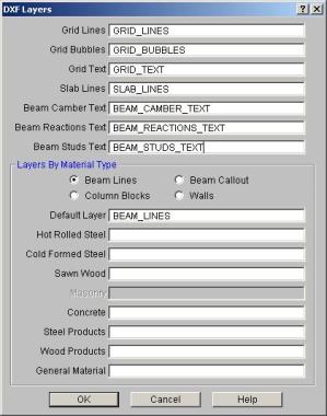
This dialog gives you layer control over the DXF file that will be created. By accessing these controls, you can create different layers for your different material types.
Different CAD packages handle ordering of geometric data in their DXF files in two basic ways.
Entities are written out into the DXF file based on the order in which they were created within the CAD program itself regardless of the order in which they were selected at the time the DXF file was made. Different operations such as copying, mirroring, arraying, etc. can produce unexpected results and it therefore becomes necessary to consult your CAD program documentation to understand how it stores and orders the geometry that you create via these various operations.
Entities are written out into the DXF file based on the order in which they were selected at the time the DXF file was made. AutoCAD is such a program. In order to control the ordering of the LINE entities, you must select the "Entities" option under the DXFOUT command and then select the lines in the order that you want them to appear in the RISA model.
The specific DXF file that you may read and write is the ASCII Drawing eXchange Files (DXF) file. Please note that AutoCAD has several different forms of DXF files available. ASCII is the default form. The DXF read/write feature was written based on the DXF documentation for AutoCAD release 14.
The following is a short excerpt of the AutoCAD ASCII DXF format. This information is provided to help you debug any problems you may be having with DXF files that you are trying to read. For more complete information, consult your CAD documentation.
A DXF file is composed of sections of data. Each section of data is composed of records. Each record is stored on it’s own line. Each particular item is stored as two records, the first record is a group code and the second record is the data or a keyword. RISA only reads the ENTITIES section.
Each 2 record item start with an integer group code. RISA recognizes the following group codes:
| Group Code | Description |
|---|---|
|
0 |
Identifies the following overall keywords: SECTION, ENDSEC, and EOF. Within the ENTITIES section it also identifies POINT, LINE, BLOCK, and INSERT. |
|
2 |
Identifies a section name (I.e., ENTITIES, BLOCKS) |
|
8 |
Identifies a layer name. |
|
10, 11, 12, 13 |
Identifies the X coordinate of the 1st, 2nd, 3rd and 4th points of an item. |
|
20, 21, 22, 23 |
Identifies the Y coordinate of the 1st, 2nd, 3rd and 4th points of an item. |
|
30, 31, 32, 33 |
Identifies the Z coordinate of the 1st, 2nd, 3rd and 4th points of an item. |
Each DXF file must start with the first record as the group code “0”. The 2nd record must be the keyword “SECTION”. Each DXF file must have the 2nd to last record as the group code “0". The last record must be the keyword “EOF”.
The ENTITIES section will be identified by a group code of “0”, followed in the next record by the keyword “SECTION”. The next record will be the group code 2, followed in the next record by the keyword “ENTITIES”.
The POINT format is started by a group code of “0” followed by the keyword “POINT”. The layer name for the POINT will start with a group code record of 8, followed by a record with the actual layer name.
The coordinates for the point will be started by the 10, 20, and 30 group codes respectively for the X, Y, and Z coordinates. Other group codes and data may be present within the POINT data but these will be ignored.
The LINE format is started by a group code of “0” followed by the keyword “LINE”. The layer name for the LINE will start with a group code record of 8, followed by a record with the actual layer name.
The coordinates for the first point will be started by the 10, 20, and 30 group codes respectively for the X, Y, and Z coordinates. The coordinates for the second point will be started by the 11, 21, and 31 group codes respectively for the X, Y, and Z coordinates. Other group codes and data may be present within the LINE data but these will be ignored by RISAFloor.
The BLOCK format is started by a group code of “0” followed by the keyword “BLOCK”. The layer name for the BLOCK will start with a group code record of 8, followed by a record with the actual layer name.
The coordinates for the definition point of the block will be started by the 10, 20, and 30 group codes respectively for the X, Y, and Z coordinates. Other group codes and data may be present within the BLOCK data but these will be ignored by RISAFloor.
The only valid characters in an AutoCAD layer name are the letters A to Z, the numbers 0 to 9, and the three following characters: the dollar sign “$”, the underscore “_”, and the dash “-”.